4 element Yagi-Uda antenna for the 2-meter band
#RadioThe previous post describes my adventures in receiving SSTV images from the International Space Station. A few days ago another SSTV event was announced, so I need to hurry up and build a better antenna. The tape-measure Yagi that I built last time worked more or less well, but was not very portable. So I want to build an antenna that is more portable and robust.
Since satellites and space stations transmit at low power and are high up in the sky, it should again be a directional antenna in order to achieve a high gain. So the Yagi-Uda design remains.
There are many different calculators for Yagi-Uda antennas on the internet, but they all give different results without much explanation. However, computer-aided antenna modeling has been around for 50 years now. The generic term NEC covers a range of computer programs that can numerically simulate the electromagnetic fields around an antenna. Unfortunately modeling an antenna in them is very cumbersome. The tooling is still based on the punched-card input format of the original software. Hence, I have written a small JavaScript program to generate the NEC files for my Yagi-Uda antenna.
This script can be tried out with the subsequent form.
I played with the script for a whole day and found a set of parameters that have a promising radiation pattern and give an acceptable calculated SWR in Xnec2c. They are set as default values in the form above.
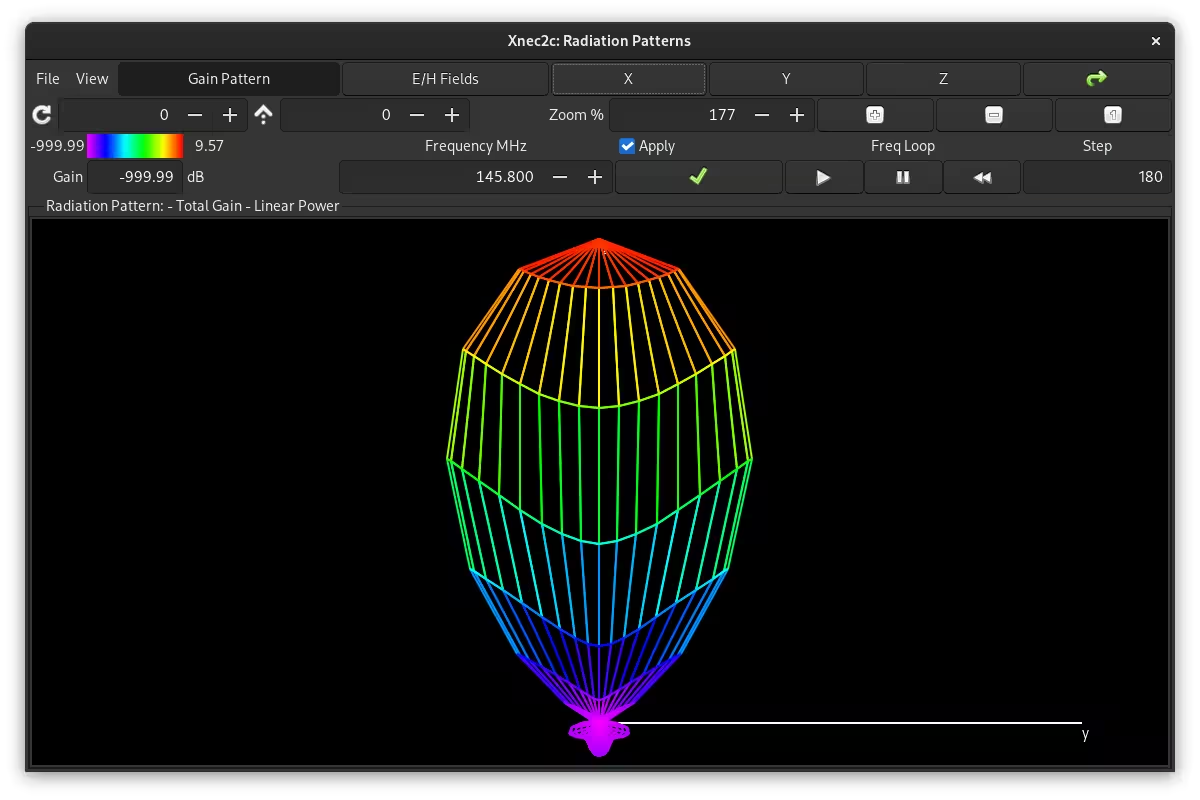

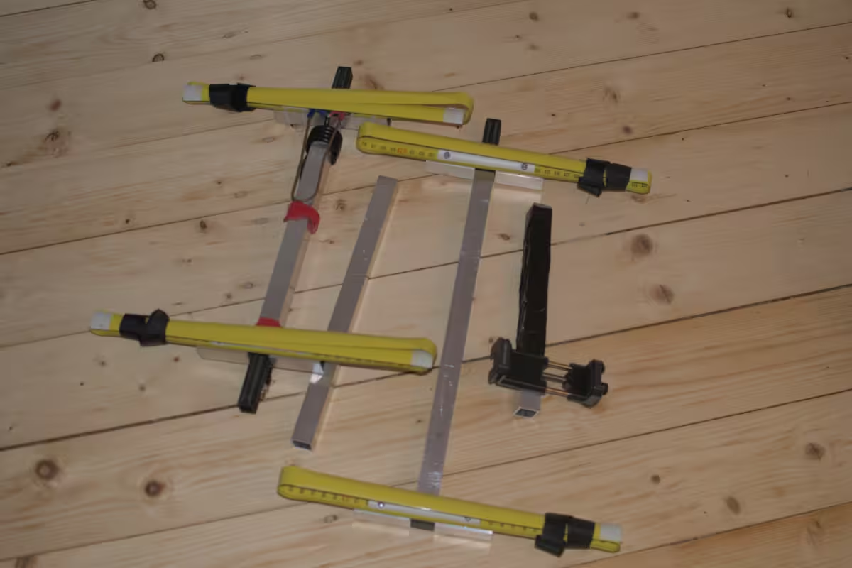
So I decided on this design and built the antenna. Almost all the parts came from the local hardware store. The boom of the antenna consists of a 20x20 mm aluminum profile and plastic connectors at each element. In addition, the elements themselves are made out of standard tape measure with a metal core.

After cutting the parts and assembling the antenna, its SWR was measured with a NanoVNA. Sadly, the resonance frequency of the antenna was slightly above the 2-meter band at 147 MHz.
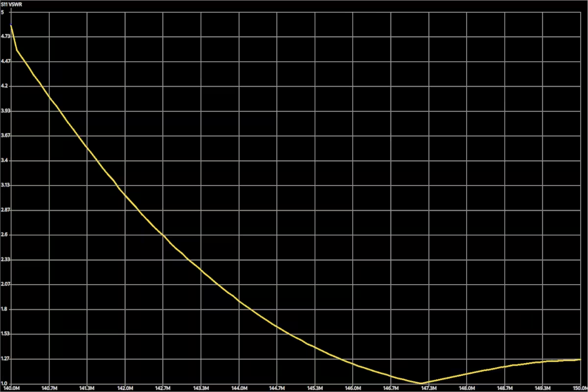
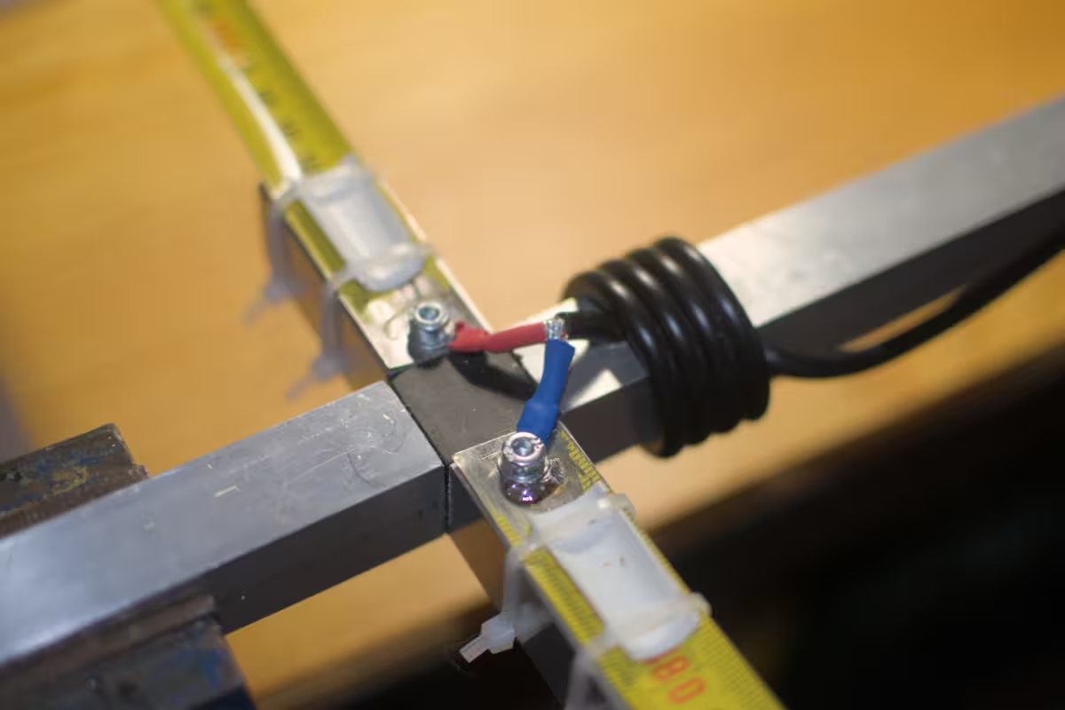
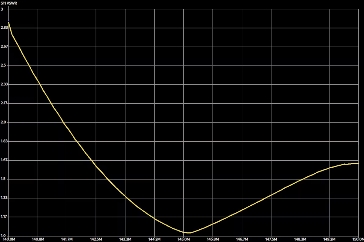
I adjusted the antenna by adding a beta match between the two connectors of the driven element. After experimenting a bit with the length, I got a nice SWR below 1.20 over the whole 2-meter band and the antenna resonates at 145 MHz. Still, I recognize that a good SWR is not synonymous with good antenna performance, but it is nevertheless a decent indicator.

Since this antenna is highly directional, it should generally be pointed toward the source of the transmission. For this reason, I have added a smartphone mount to its boom, as there are many apps for phones that help with tracking satellites or space stations.

With the boom not being continuous, but separated into several parts that are held together by the plastic connectors, the antenna can be disassembled into multiple parts. And as an additional feature, the individual parts fit easily into a backpack.
As a final rehearsal, I tested the antenna with a transmission from the CubeSat Sonate-2. This satellite, launched by the Julius Maximilian University of Würzburg, will be actively transmitting SSTV from October 15, 2024 to October 18, 2024. Since its transmission power of 500 mW is rather low, it is well suited as a test object for the reception performance of the antenna.
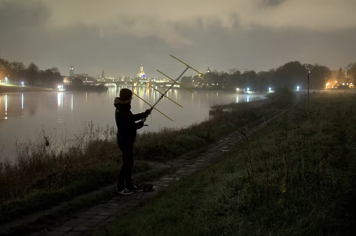
In the end, the antenna performed really well. With my smartphone mounted on the boom running Look4Sat and SDR++, the satellite could be tracked with ease and I received a strong signal. (The following video is accelerated 2x)
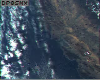
The resulting images are significantly better than my previous attempts to receive transmissions from Sonate-2 with either a V-dipole or a QFH antenna. The callsign DP0SNX is clearly recognizable and there are almost no visual artifacts in the resulting images: